


Optical Flow
The Optical Flow node can used to calculate dense optical flow fields describing the apparent motion of objects relative in the camera plane.
Optical flow fields contain a vector at every pixel that describes where that pixel moves to in the next or previous frames.
The data generated by the Optical Flow node can be used down-stream by the Retime node to perform retiming of both image and camera motion data, or exported by the Footage Export node.
Painting tools are available that allow small corrections to be made to the optical flow fields, and masks can be used to define object boundaries and increase the accuracy of the optical flow calculations.
Note that optical flow describes the apparent motion of objects in the camera plane, which is not necessarily the same as the actual object motion. For example, a camera viewing a flat evenly illuminated surface may produce images which have no significant differences from frame-to-frame, even though the camera is actually moving relative to the surface. In this case, the apparent motion is zero even though the true motion is non-zero.
As optical flow is calculated, data files are written to disk containing flow information for every pixel. To conserve space, the flow fields are quantised to a user-defined degree and compressed. For a typical 2048x1556 image, the amount of disk space required for each flow field is roughly as follows:
- 1 pixel: 0.5Mb per frame and direction
- 1/4 pixel: 1.5Mb per frame and direction
- 1/16 pixel: 3.5Mb per frame and direction
- 1/64 pixel: 7.5Mb per frame and direction
- 1/256 pixel: 11Mb per frame and direction
Usage
Optical flow is calculated from one frame of a clip into both the previous and next frames. This provides bi-directional optical flow data that can be used to retime both image and motion data.
The area of each frame for which optical flow will be calculated is defined by the region of interest (ROI). This can be adjusted to remove unwanted areas from the edge of each frame.
Using Masks
Masks can be used to exclude areas of the image from the optical flow calculation, or to indicate boundaries between different moving objects. Each mask that is piped in the node will appear in the Mask list, where its behaviour can be controlled. The ordering of individual masks is important, because it specifies the relative depth ordering of the objects defined by each mask, and therefore defines the way an object moves in front or behind the others. Masks at the top of the mask list define objects that are farther away from the camera than masks at the bottom of the list.
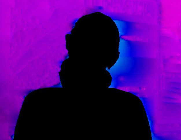
When a mask is set to Exclude, pixels covered by the mask will be excluded from the optical flow calculation. The following example shows how an exclude mask is used placed around an actor, and the resulting flow field displayed as direction and magnitude.
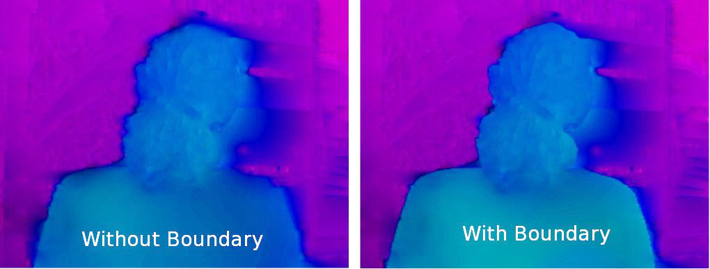
When a mask is set to Boundary, pixels covered by the mask are assumed to belong to an object which is moving independently from the pixels outside the mask. Boundary masks can prevent smoothing between areas of the image inside and outside the mask. The example below shows the optical flow fields obtained without (left) and with (right) a boundary mask. Note the improved optical flow definition along the actor's shoulders.
Viewing Optical Flow
Once optical flow data has been calculated, it can be viewed in the Cinema window using a variety of options available in the Display controls. Either the forwards or backwards flow fields can be displayed, and the flow vectors can be represented as either vectors or pixel colours encoding data such as the direction and magnitude of each vector. The screenshot below shows an optical flow field displayed as vectors (on the left), and with direction (middle) and magnitude (right) colour-coded pixels.
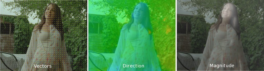
Flow directions are represented using varying hues representing angles from 0 to 360 degrees, and flow magnitude is represented as a range from black to white, where black indicates zero magnitude. More details on the parameters used to affect the display of flow data are given below in the Controls section.
As well as displaying either vectors or pixel colours, an in-between frame can be generated to test the quality of retiming (see the Retime node documentation for more details on how to retime clips and camera/tracker/object motion). This can be useful when editing optical flow data to improve the accuracy of retiming in certain parts of a frame (see below).
Editing Optical Flow
In some cases, the automatic optical flow algorithm may not be able to estimate flow in certain parts of the image as accurately as in other parts. This can affect the quality of retimed image data, and in situations like these, manual painting tools are available to help correct the flow data.
Several editing modes are available: Paint, which will attempt to track the painted region into the next or previous frame and fill in the flow vectors accordingly; Clone, which can be used to copy flow vectors from one part of the frame to another; Smooth, which can be used to smooth flow vectors in a certain region; and Erase, which can be used to add or remove occlusions to help resolve the relative depths of objects from the camera and improve rendering around object boundaries.
Controls are available to adjust the shape, size and softness of the brush, as well as the search area used by the Paint brush mode.
Further details on the editing controls are given below.
Controls
Current clip: The clip that is being displayed in the Cinema window.
Masks
Columns
Name: The name of each active mask.
Colour: The mask overlay colour for each active mask. Double click in this column of the selected mask to change its overlay colour.
State: When set to Exclude, no optical flow will be produced for pixels covered by the mask. When set to Boundary, no smoothing will be performed across the edge of the mask. Right-click in this column to change the behaviour of each mask to either Exclude or Boundary.
Buttons
Move Closer: Move the selected mask closer towards the camera. Note that the ordering of masks is important only if they overlap.
Move Away: Move the selected mask away from the camera. Note that the ordering of masks is important only if they overlap.
Solver
Clips: The clips to calculate optical flow for. All clips will generate flow fields for all clips connected to the node. Current clip will generate flow fields for the clip that is displayed in the Cinema window only.
Frame range: The processing range for optical flow calculation. Options are Clip, to generate a flow field for each frame in the clip; From/To to generate flow fields for a specific range of frames; and Current to generate a flow field for the current frame only. Note that when generating a field for the current frame only, optical flow will be calculated from the current frame to both the previous and next frames.
From: Set the From frame to the current frame when the Frame range is set to From/To. The frame number can also be adjusted in the edit box.
To: Set the From frame to the current frame when the Frame range is set to From/To. The frame number can also be adjusted in the edit box.
Channels: Which of the red, green and blue image channels to use when estimating optical flow.
Smoothness %: The amount of smoothing to apply between adjacent areas in the image. Increasing this value will produce smoother optical flow estimates.
Accuracy: The time/accuracy tradeoff in the optical flow calculation algorithm. Options are Normal; Low, which will produce a lower accuracy field more quickly; and High, which will produce a more accurate field than Normal but will require longer processing time.
Quantization: This menu specifies the amount of quantisation to use when storing flow data to disk during the optical flow calculations. Quantisation options range from 1 Pixel to 1/256 Pixel, where 1/256 Pixel will store data accurate to 1/256th of a pixel.
Edit ROI: Allow the region of interest (ROI) to be edited. The ROI specifies the area of the image for which depth values will be estimated. Note that if your clip has border areas that do not contain image data it is important that the ROI is adjusted accordingly to remove these areas from the calculation. When enabled, click and drag with the left mouse button in the Cinema window to adjust the ROI boundary.
Use Tracker hints: When enabled, 2D tracker paths will be used to provide hints to the optical flow calculation algorithm.
Clear: Clear all optical flow data and delete the data files from disk.
Solve: Solve for optical flow over the frames specified by the Frame range.
Display
Direction: Display of either the forward or backward flow fields in the Cinema window.
Overlay: The type of overlay that is displayed in the Cinema window. Options are None, to display no overlay; Vectors, to display a set of vectors; Pixels, to display an overlay with flow data encoded as pixel colours; and In-Between Frame, to display a retimed in-between frame.
Colour: The way optical flow data is encoded as colour when displaying either a Vector or Pixels overlay. Options are Fixed, to display with a fixed colour that can be changed by clicking the coloured button on the right; Quality, whereby the matching accuracy of the optical flow is encoded as green (good quality) and red (bad quality); Occlusions, where occluded pixels are displayed as white and unoccluded pixels as black; Direction, where the flow vector direction is encoded as colour hue; Magnitude, where the flow magnitude is encoded as black (zero magnitude) to white; and Dir+Mag, which combines the Direction and Magnitude options together, encoding direction as hue and magnitude as intensity.
Density: The density of displayed vectors when using the Vectors overlay type. Dragging the slider to the right will increase vector density, which will show more detail in the overlay but may cause a drop in rendering performance. This control has no effect on the actual optical flow data stored on disk, and is only for display purposes.
Transparency %: The transparency of the Pixel overlay type. A value of 0 will show a solid overlay, and a value of 100 will show a fully transparent overlay.
Scale: The scale that is used to draw the Vector overlay, and the scale that is applied to the flow vector magnitude when using the Magnitude colour mode. The default value is 1.0 which means the vectors and magnitude will be shown at their original scale.
Time: The sub-frame position at which the In-Between Frame overlay will be generated. Values can range from 0.0 to 1.0, where time 0.0 corresponds to the current frame, and time 1.0 corresponds to either the next or previous frame, depending on whether the Direction option is set to Forwards or Backwards.
Swap Field: Change the frame number and Direction option to display the matching half the bi-directional flow fields associated with each frame. For example, if you are viewing frame 10 in the Forwards direction, clicking this button will display frame 11 in the Backwards direction. This can be useful when editing optical flow fields using the paint tools to ensure that the flow vectors are correct in both directions.
Editing
Shape: This menu can be used to choose a brush shape for painting optical flow data. Options are Circle, Ellipse, Square and Rectangle.
Size: The horizontal and vertical size of the paint brush. The vertical size edit box is only available when using either the Ellipse or Rectangle brush shapes. Brush size can also be adjusted interactively in the Cinema window by holding the Option key and clicking and dragging with the left mouse button.
Softness %: The softness of the paint brush, measured from 0 to 100 where 0 indicates a hard brush.
Search Size: The size of the search region (measured in pixels) that is used when trying to estimate flow vectors for painted pixels. This is only available when using the Paint brush mode.
Respect Occlusions: When enabled, the brushes will respect occluded pixels. For the Paint, Clone and Smooth brush, this means that the occlusion states for painted pixels will be maintained.
Respect Mask Boundaries: When enabled, the brushes will respect mask boundaries so the only pixels that are painted are the ones belonging the the mask at the centre of the brush when first clicking with the left mouse button.
Paint Forwards And Backwards: When enabled, any editing operation will be applied to both the forwards and backwards half of the bi-directional flow data. The Swap Fields button can be used to quickly switch between directions.
Paint: Enable the Paint brush. Clicking and dragging with the left mouse button in the Cinema window will identify a set of pixels that will then be tracked as a single area into either the next or previous frame, depending on which Direction is being viewed. The search range used for tracking is controlled by the Search Size edit boxes. To specify the location to search when tracking, hold the Control key and click and drag with the left mouse button. The red brush outline indicates the area that will be searched in either the next or previous frames to find the best matching set of pixels.
Clone: Enable the Clone brush. To clone flow vectors, click and drag with the left mouse button in the Cinema window. To adjust the clone offset, hold the Control key and click and drag with the left mouse button.
Smooth: Enable the Smooth brush. To smooth flow vectors, click and drag with the left mouse button in the Cinema window.
Erase: Enable the Erase brush, which can be used to add or remove occlusion flags. Clicking and dragging with the left mouse button in the Cinema window will enable occlusions at each pixel. To remove occlusions, hold the Control key whilst clicking and dragging with the left mouse button.
Default Keyboard Shortcuts
| Move Closer | Shift+N |
| Move Away | Shift+M |
| Edit ROI | Shift+E |
| Clear | Shift+L |
| Solve | Shift+S |
| Display: Backwards | [ |
| Display: Forwards | ] |
| Overlay: None | Control+N |
| Overlay: Pixels | Control+X |
| Overlay: Vectors | Control+V |
| Overlay: In-Between Frame | Control+I |
| Colour: Fixed | Shift+F |
| Colour: Quality | Shift+Q |
| Colour: Occlusions | Shift+R |
| Colour: Direction | Shift+D |
| Colour: Magnitude | Shift+A |
| Colour: Dir+Mag | Shift+C |
| Swap Field | S |
| Shape: Circle | Shift+O |
| Shape: Ellipse | Shift+I |
| Shape: Rectangle | Shift+T |
| Shape: Square | Shift+U |
| Respect Occlusions | Control+D |
| Respect Masks | Control+M |
| Paint Forwards And Backwards | Control+B |
| Paint | Control+P |
| Clone | Control+C |
| Smooth | Control+S |
| Erase | Control+E |