Example Tree Layouts
This chapter shows some example tree layouts that can be used for solving cameras. Note that tracking jobs can often be completed using various different combinations of nodes. The trees described below are for illustrative purposes only, and are not necessarily the only way each type of task can be completed.
A simple example
In the first example, the Clip Input node provides the image data, and defines the camera in the scene:
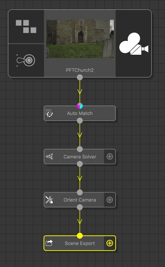
Data flows down the tree from the Clip Input. The first node attached to the Clip Input is an Auto Match node, which automatically generates some feature tracks for the clip.
The Camera Solver node then uses these feature tracks to estimate the motion of the camera in the shot.
The Orient Camera node is then used to set the overall scale and orientation of the solved camera and point cloud, and finally the Scene Export node is used to export all the data to an external file.
A more complex example
The second example is more complex, and illustrates how multiple clips can be used in a single tree.
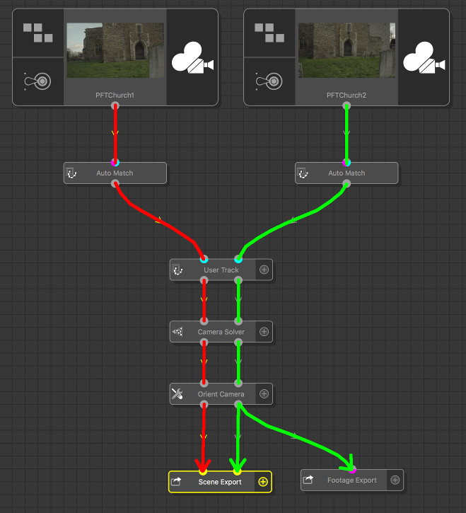
Both cameras are viewing the same scene from different angles, and the aim here is to solve both cameras into the same 3D space, so they are positioned correctly relative to each other.
The Clip Input nodes provide the image data viewed by both cameras. Data flows from each Clip Input down the tree until it reaches either a Scene Export or Footage Export node, and is modified by each node it passes through.
Each clip is passed through an Auto Match node to automatically generate tracking points. Note that these tracking points are entirely independent, and only associated with a single input clip.
A single User Track node is the created with both clips connected to it. This User Track node is able to generate additional trackers, and position each tracker in both input clips. This is important, because it means that one feature point in the scene (such as a corner of a brick or window) is associated with a tracker in each clip.
The first output of the User Track node contains the tracker paths associated with the first input clip, and similarly for the second output. Because both sets of tracker paths were generated by the same User Track node, when they are piped into the Camera Solver node, they can be used to solve both cameras at the same time, ensuring that each camera views the same 3D tracker positions.
Note that there are two export nodes in this example: The first is a Scene Export node, which exports the cameras generated for both clips in a single scene file. The additional Footage Export node only input from the second clip, and therefore cannot access any data from the first clip.